 Vulkan Research
Build Orion, step by step
This guide takes you from a pile of printed parts to a lamp that moves, listens and lights up. Every step says which screws to use, shows where the new parts go, and explains why it is done that way.
On a wide screen, the 3D view beside the steps follows along as you scroll. Parts added in the current step are orange, printed parts are white and bought parts such as servos and boards are grey. Drag the view to turn it. Cables aren't in the 3D model; the text says where they go.
Before you start
The build has five stages: prepare the parts and software, build the base, build the shoulder and arms, build the head, then wire it up and bring it to life. Printing takes a few days of printer time; the assembly itself is a few evenings of screwing, plugging and a little soldering. You don't need to have built a robot before.
What you need
- Printed parts: every file in the STL download, with the flush plug printed 16 times.
- Electronics, cables and screws: the bill of materials. Sort the screws into labelled pots by size before you begin; it saves a lot of hunting.
- A computer to prepare the Raspberry Pi's memory card and connect to it over the network (step 4).
Tools
- Soldering iron with an M3 heat-set insert tip, plus solder for the LED ring wires
- 2 mm hex key for the M3 button-head screws
- Small screwdrivers to suit your M2 and M2.5 screws and the servos' centre screws
- 3.4 mm and 2.4 mm drill bits, turned by hand (a pin vice is ideal)
- Flush cutters or small pliers for removing supports
- A 2 mm rod, such as the smooth end of a drill bit, for bending servo wires
Safety Unplug both power supplies before connecting or disconnecting anything. Once powered, the joints are strong enough to pinch fingers.
Ideas and words used in this guide
- Reading a screw size
- “M3 × 6” means a 3 mm thread that is 6 mm long, measured from under the head to the tip. Orion uses button-head screws for the M3 joints: they have a low, rounded head and take a 2 mm hex key.
- Heat-set inserts
- Plastic threads wear out quickly. A heat-set insert is a small brass sleeve with a metal thread inside. You press it into a printed hole with a hot soldering iron; the plastic melts around its knurled outside and grips it as it cools. Screws then thread into metal, so you can take the robot apart again and again.
- Receiving holes
- The small M2 and M2.5 screws don't need inserts. They go into slightly undersized holes (1.9 mm for M2, 2.2 mm for M2.5) and cut their own thread in the plastic. Turn them in by hand and stop as soon as they are snug; overtightening strips the thread.
- Servo horns and faces
- A horn is the round metal plate on a servo's output. The driven horn turns with the motor and is held on by a centre screw that comes with the servo; the passive horn on the opposite side just carries load. Arm parts bolt to both, so each joint is supported from two sides. The servo's gear face is the side with the copper-coloured gear horn; the plain face is the opposite side.
- Serial bus servos
- Orion's five STS3215 servos share one cable, like beads on a string: each servo has two sockets, one for the cable coming in and one for the cable going on to the next servo. Each servo also has an ID number, and the controller addresses them by that number. That is why the servos get their IDs in step 5, before they are built into the lamp, and why you plug the chain together as each servo goes in.
- Other words
- A boss is a raised round post that a screw or insert goes into. A counterbore is a wider, shallow step at the top of a hole that lets a screw head sit below the surface. A flange is a flat rim around a part that it is screwed down by. A ribbon cable is the flat, wide cable the camera uses.
| Servo ID | Joint | What it moves |
|---|---|---|
| 1 | Base yaw | Turns the whole lamp |
| 2 | Shoulder | Tilts the lower arm |
| 3 | Elbow | Tilts the upper arm |
| 4 | Wrist | Tilts the head up and down |
| 5 | Neck | Turns the head left and right |
In this guide the lower arm is the arm on the shoulder and the upper arm is the one on the elbow, as in the CAD files.
Stage 1 of 5 · steps 1–5Prepare
Print and clean the parts
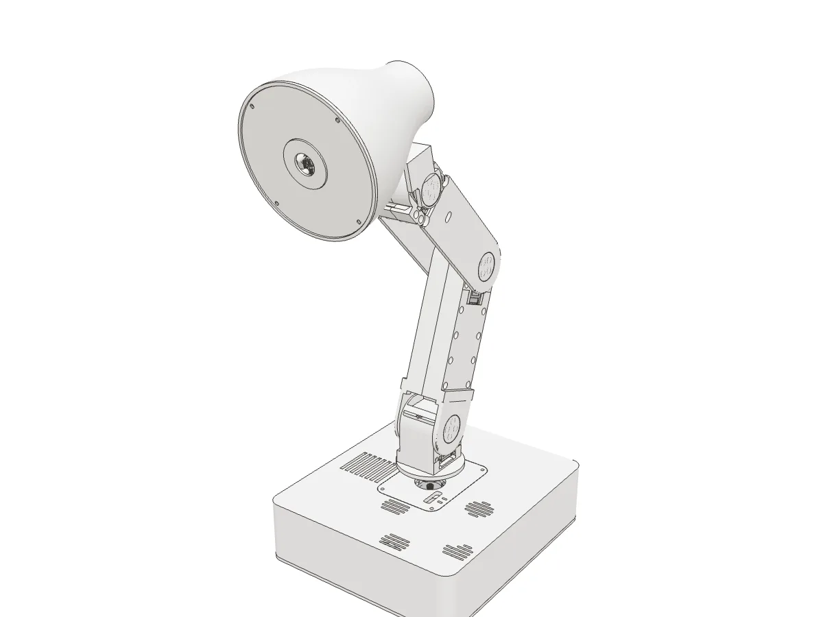
Print every file in the STL download in PLA, keeping each file's orientation. The settings below are the ones the CAD's print plates use; the arms need the most strength, so don't skimp on their walls.
| Parts | Walls | Infill | Supports |
|---|---|---|---|
| Arm halves (10, 13) and plugs | 5 | 25% gyroid | From the build plate only |
| Base shell (01) | 4 | 20% gyroid | Tree supports, 5 mm brim |
| Bottom cover (02), tray (03) | 4 | 20% gyroid | None |
| Base fittings (04, 04b, 05, 06, 07) | 5 | 35% gyroid | Tree supports |
| Shoulder (08, 09) | 5 | 40% gyroid | Tree supports, 5 mm brim |
| Head shell, fork, cartridge (16, 17, 19) | 5 | 30% gyroid | Tree supports, 5 mm brim |
| Front parts and caps (18, 20, 22, 24) | 4 | 20% gyroid | Tree supports where needed |
| Diffuser (21) | 4 | 20% gyroid | None; use a light-coloured filament that lets light through |
All parts: 0.2 mm layers, 0.4 mm nozzle.
Once a part has cooled, remove all support material and brim, paying most attention to the places other parts have to fit: insert holes and screw recesses, the round horn seats, the cable channels inside the arm halves, and the camera opening.
Careful Don't drill out the small 1.9 mm and 2.2 mm screw holes to "clean" them. They are undersized on purpose so the screws can grip.
Open the thin screw-hole skins
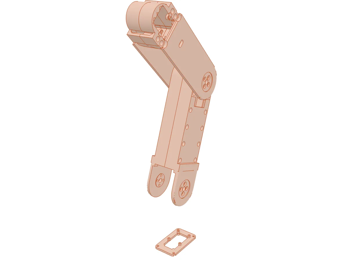
- 1× 3.4 mm drill bit
- 1× 2.4 mm drill bit
Some screw holes are printed with a 0.2 mm skin across them. The skin lets the printer bridge cleanly over the hole; you open it afterwards by hand.
- In the four arm halves, open all 16 counterbore skins with the 3.4 mm bit. These are the holes for the M3 seam screws.
- In the yaw servo retainer (part 04b), open the 4 counterbore skins with the 2.4 mm bit.
Tip Turn the bit slowly between your fingers. A power drill grabs the thin skin and can crack the part.
Fit the heat-set inserts
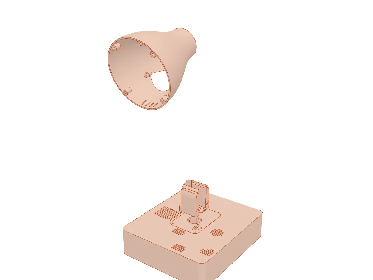
- 40× M3 heat-set inserts, 4 mm long
Fit every insert now, while the parts are empty. Heat from the iron can damage electronics, and the holes are easier to reach.
| Part | Inserts | How |
|---|---|---|
| Base shell (01) | 14 | 6 for the bottom cover, 4 for the tray, 4 for the yaw carrier. Put the carrier inserts in from inside the shell with the shell upside down, flush with their bosses. Leave the small gap below them; don't push them onto the floor. |
| Yaw servo carrier (04) | 4 | For the retainer screws. |
| Power panel (05) and USB panel (06) | 4 each | From the inside face, into the four raised bosses. |
| Shoulder housing (08) | 6 | Four for the yaw adapter, two for the retainer. |
| Head shell (19) | 8 | Through the open front. Do the four deeper ones first, then the four near the rim. |
- Set the iron to the temperature your insert maker recommends.
- Sit the insert on its hole, then lower the hot tip into it and let it sink under its own weight with light pressure. Keep the iron square to the surface.
- Stop when the top of the insert is flush with the plastic, lift the iron straight out, and let the part cool before fitting any screws.
Check Insert holes are 4 mm across; plain screw holes are 3.4 mm. If an insert won't start, you may be on a screw hole. If an insert spins when you turn a screw, or the boss cracks, reprint the part rather than gluing the insert.
Set up the Raspberry Pi
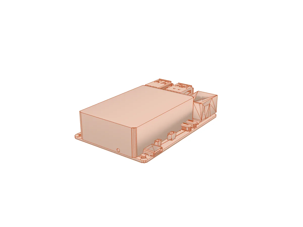
The Orion software runs on the Raspberry Pi. Install it now, on the table, so you can set up the servos in the next step. The Orion quickstart has the full details.
- Fit the Active Cooler to the Pi, following its instructions.
- On your computer, use Raspberry Pi Imager to write Raspberry Pi OS Lite (64-bit) to the Pi's memory card. In Imager's settings, set a hostname, a user, your Wi-Fi and an SSH key.
- Put the card in the Pi, power it with its USB-C supply, and connect from your computer:
ssh USER@HOST.local - Install Orion, then restart the Pi:
curl -fsSL https://raw.githubusercontent.com/mofe64/orion/main/scripts/install.sh | bash
sudo reboot
Good to know On a first install the Orion services are left stopped, so nothing moves while you set up the servos.
Give each servo its ID
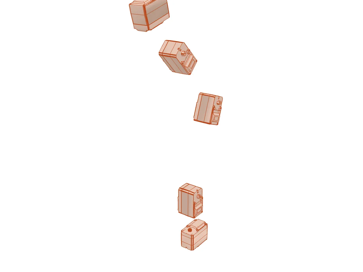
The picture shows where the five servos end up. New servos all share the same ID, so the controller can't tell them apart. Give each one its own ID while you can still plug them in one at a time. This also tests every servo before it goes into the lamp.
- Connect the servo board to the Pi with its USB cable, and plug the 6 V supply into the servo board. The servos are powered from the board, not from the Pi.
- Plug in one servo and give it its joint. For example, for the shoulder:
It answers with the old and new ID, for exampleoriond servo set-id --joint shoulder_pitch_jointservo ID 1 -> 2; verified. - Unplug the servo, label it with tape (“2 shoulder”), and repeat for the other four. The joint names are
base_yaw_joint,shoulder_pitch_joint,elbow_pitch_joint,head_pitch_joint(wrist) andhead_roll_joint(neck).
One at a time If it says “Expected exactly one servo”, more than one servo is plugged in, or none is (check the 6 V supply). If it says “Expected one USB servo adapter”, the servo board's USB cable isn't connected.
Stage 2 of 5 · steps 6–12Build the base
Work with the base shell upside down on a soft cloth until step 12.
Fix the base servo to its retainer
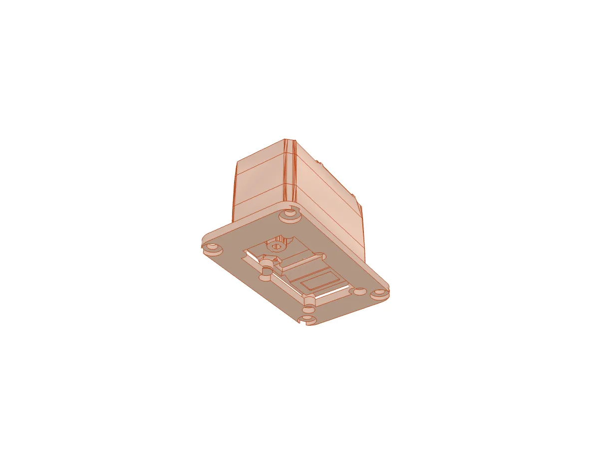
- 4× M2 × 6 screws
The base servo (ID 1) turns the whole lamp. It stands upright with its output facing up, and a flat retainer frame (04b) is screwed to its underside.
- Hold the retainer with its raised pads facing up, against the servo's underside.
- Fit four M2 × 6 up through the retainer into the servo. The screw heads sit just inside the retainer's underside.
- Plug a servo cable into the servo now; it will run to the servo board in step 10.
Push the servo into its carrier
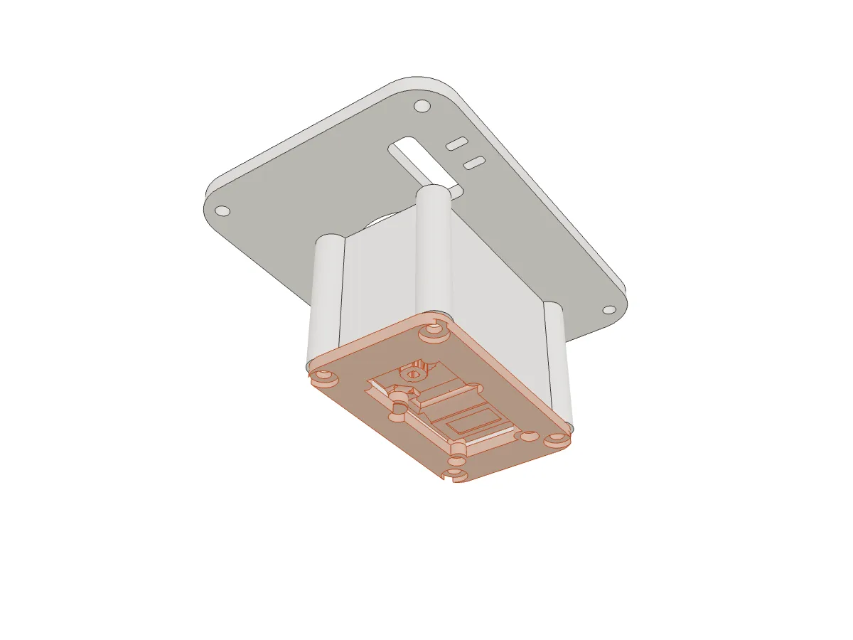
- 4× M3 × 6 button-head screws
- Hold the carrier (04) upside down and push the servo and retainer into it with firm hand pressure, servo first, until the servo sits against the carrier's roof. Small ribs inside the carrier hold it without play; they may shave a little, which is expected.
- Fix the retainer to the carrier with four M3 × 6 into the carrier's inserts.
Careful Never sand the servo's case to make it fit. If it is very tight, clean the carrier ribs instead.
Fit the carrier into the base
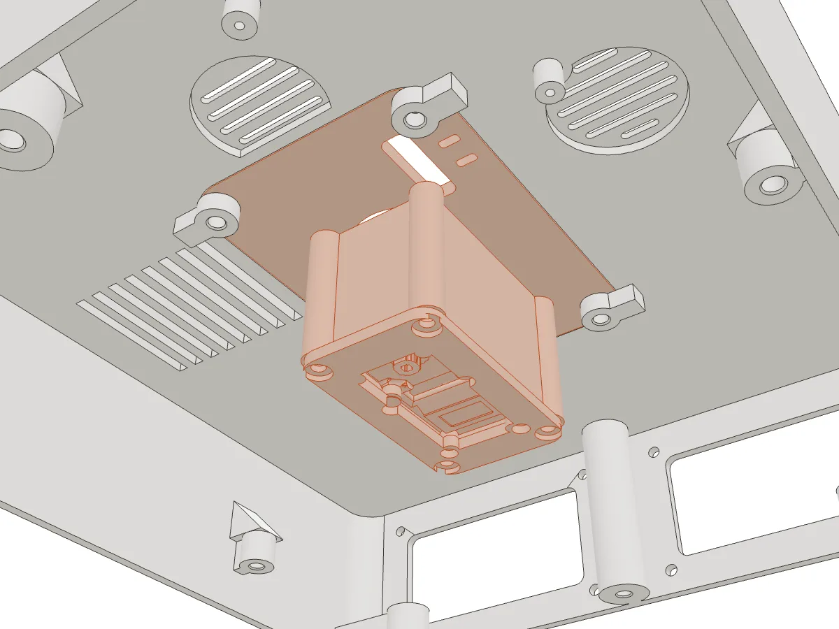
- 4× M3 × 8 button-head screws
- With the shell upside down, lower the carrier into the middle of the shell so its flange sits on the four inserts you fitted in step 3.
- Fit four M3 × 8 through the flange into the inserts.
Fit the microphone
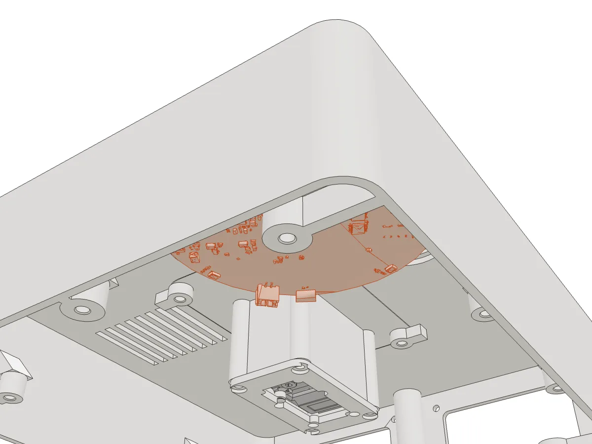
- 3× M2 × 4 screws
- 3× M2 insulating washers, 0.5 mm
The microphone array sits just under the base's roof, behind the four slotted grilles, so it can hear in every direction.
- Turn the board so its USB socket faces the front-left of the base, then rest it on its three 7 mm spacers.
- Fit three M2 × 4, each with a 0.5 mm insulating washer under its head, and tighten gently.
- Plug its USB cable into the board.
Why the washers They keep the metal screw heads off the board's circuitry and stop the short screws reaching the bottom of their holes.
Build the electronics tray
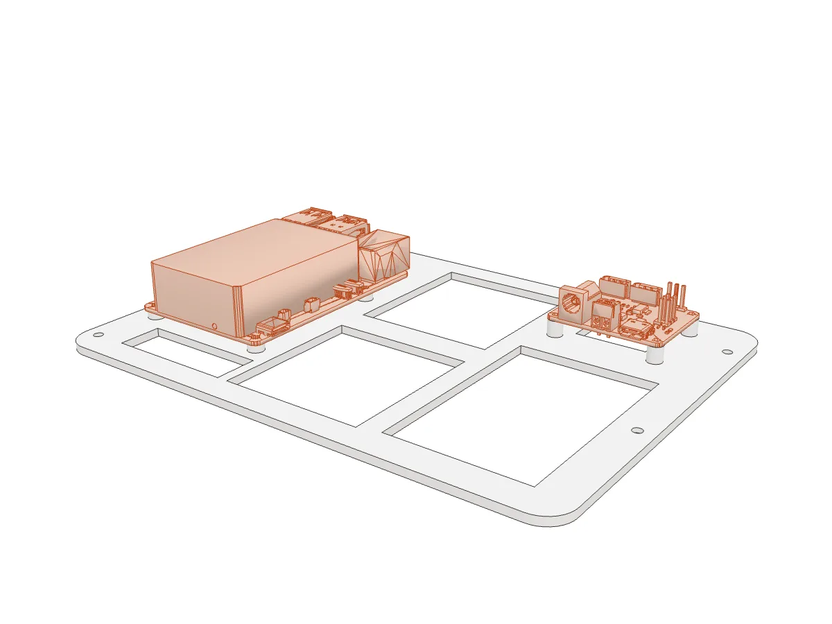
- 4× M2.5 × 4 screws (Raspberry Pi)
- 4× M2 × 6 screws (servo board)
- 4× M3 × 6 button-head screws (tray to shell)
- Screw the Pi to the tray (03) with four M2.5 × 4 into its 3 mm posts.
- Screw the servo board to the tray with four M2 × 6 into its 6 mm posts. Keep both boards flat; don't let a screw bend them.
- Connect the servo board to the Pi with its USB cable, and plug the base servo's cable into the servo board.
- Plug the microphone's USB cable into the Pi's upper USB-A socket. It bends tightly here, so lead it round in gentle curves rather than folding it.
- Lower the tray into the base and check that the cooler, plugs and cables sit without being pressed. Then fit four M3 × 6 through the tray's recessed holes.
Fit the rear panels and power leads
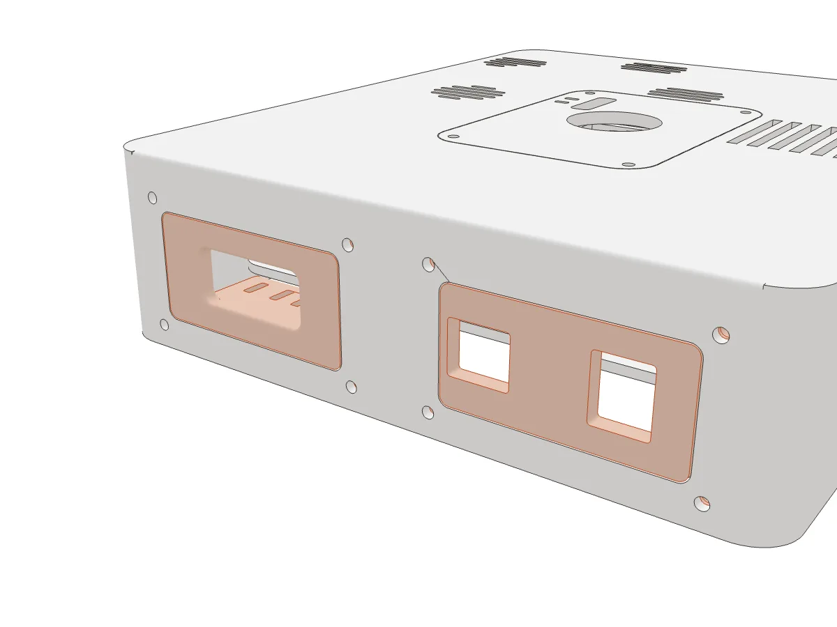
- 8× M3 × 8 button-head screws
- 2× Cable ties, 2.5 mm
The power panel (05) has one shared opening for both power leads: the Pi's USB-C supply and the 6 V servo supply. The other panel (06) gives access to the Pi's Ethernet and USB.
- Pass both power leads through the shared opening and connect them: USB-C to the Pi, the 6 V lead to the servo board.
- Tie each lead to its tie point with a 2.5 mm cable tie. Pull it snug, not tight: the tie should stop the lead being pulled out without squashing it.
- Hold each panel against the shell from the inside, inserts facing in. From the outside, fit four M3 × 8 through the shell into the panel.
Why from the outside The screws pass through the shell wall and pull the panel up against it, so the screw heads stay on the outside where you can reach them later. The camera's ribbon cable will come in through one of these panel openings in step 31, so don't block them.
Fit the yaw horn adapter
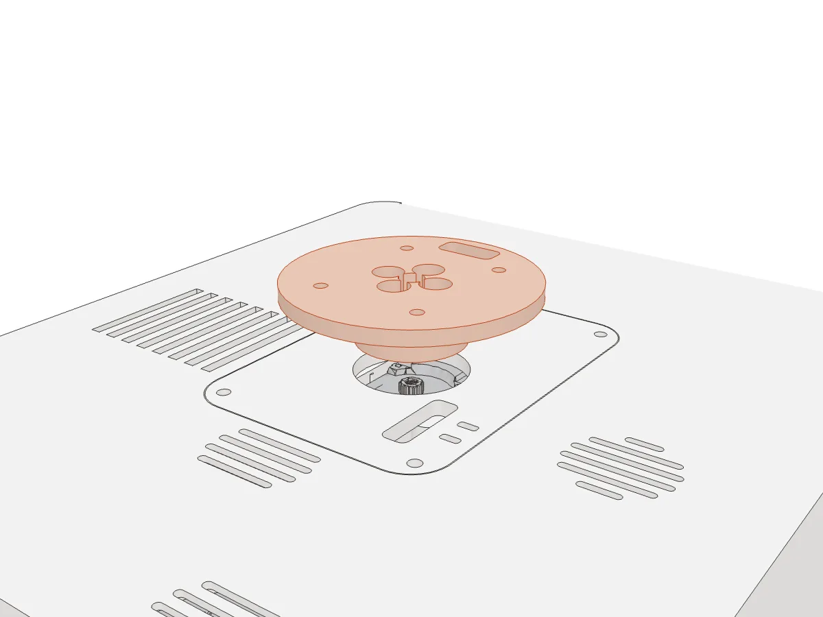
- 4× M3 × 4 button-head screws
- 1× Servo centre screw (supplied with the servo)
Turn the base the right way up. The adapter (07) connects the base servo's horn to the shoulder above it.
- Fix the adapter to the metal horn with four M3 × 4, then secure the horn with its centre screw.
- Make sure no wires are trapped between the adapter and the shell.
No need to centre the servos You can fit horns and arms at whatever angle the servo happens to be in. In the last step, Orion records each joint's position with the lamp folded and uses that as its zero.
Stage 3 of 5 · steps 13–21Build the shoulder and arms
Plug the servo chain together as you go. Once an arm is closed, you can't reach the cables inside it.
Fit the shoulder housing
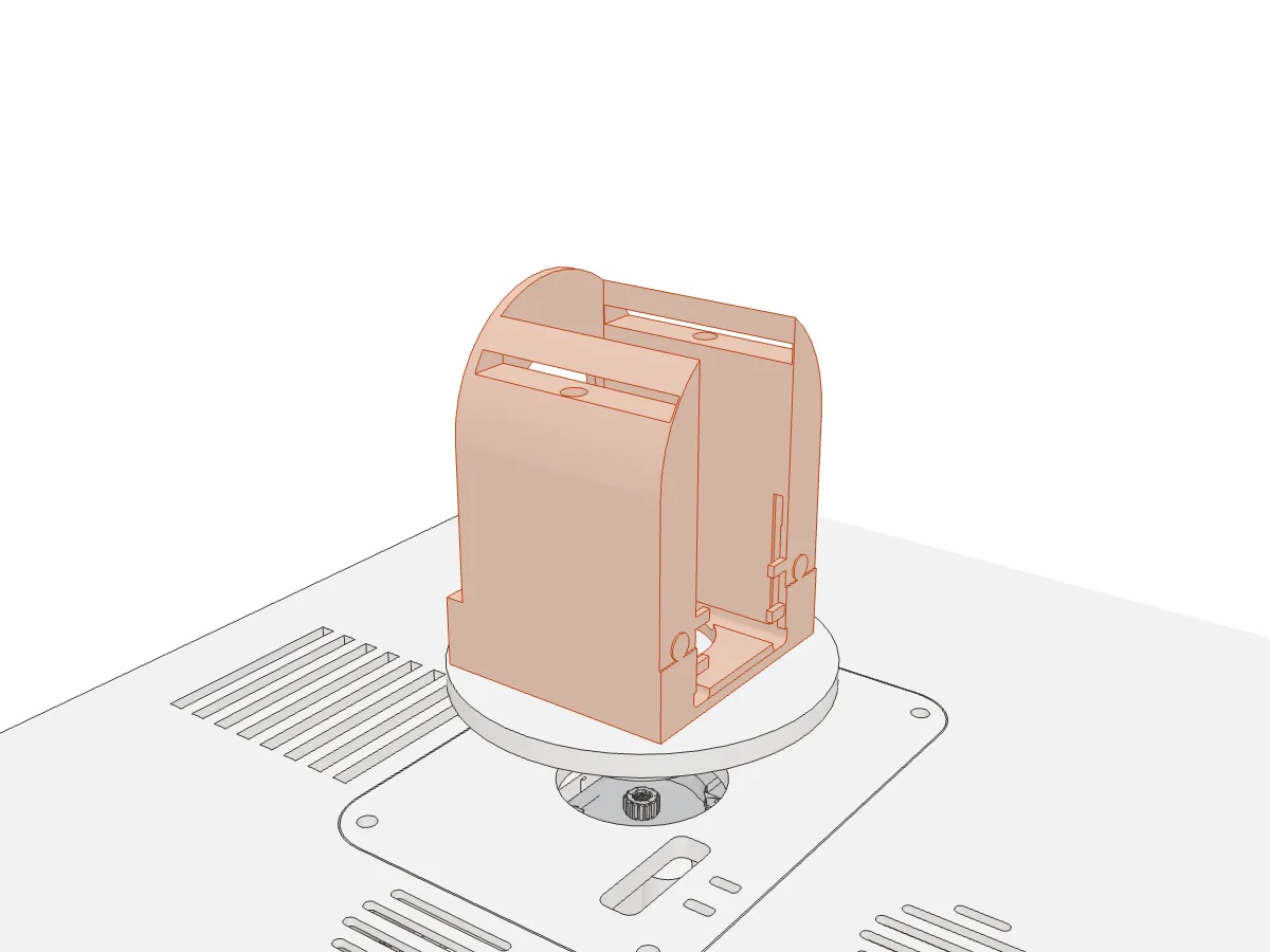
- 4× M3 × 6 button-head screws
- Fix the shoulder housing (08) to the yaw adapter with four M3 × 6 into the housing's inserts.
Put the shoulder servo in its housing
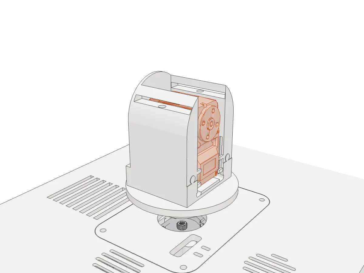
- 2× M2 × 10 screws
- Plug the cable from the base servo into the shoulder servo (ID 2), and plug a second cable into its other socket for the elbow.
- Lower the servo into the housing from above, its output pointing sideways as in the picture, so a horn sits in each side opening.
- Fit the two M2 × 10 through the housing into the servo's gear face.
- Bend the servo's wires 90° over your 2 mm rod, then route them under the small keepers and along the grooves in the housing floor.
The servo's horns, one on each side, are what the lower arm bolts to in step 18.
Fit the shoulder retainer
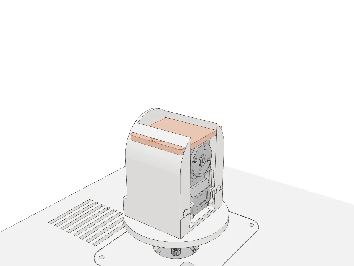
- 2× M3 × 6 button-head screws
- Lay the retainer (09) across the top of the housing, over the servo.
- Fit two M3 × 6 through it into the housing's inserts. The retainer stops the servo lifting out.
Put the elbow servo in the lower arm
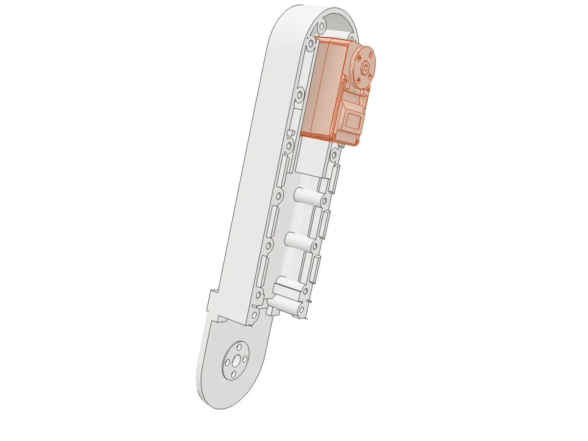
- 4× M2 × 6 screws (gear face)
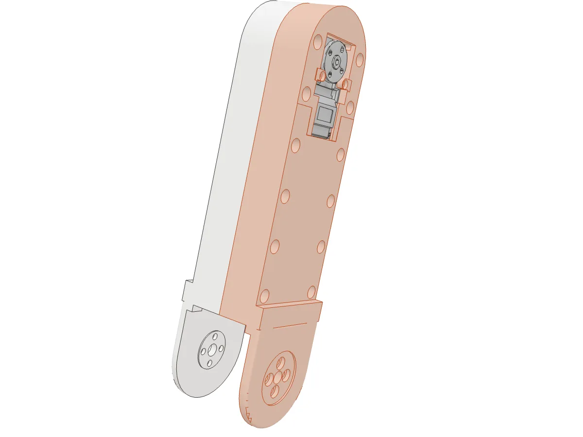
Each arm is printed as two halves that close around a servo, like a clamshell. Splitting it lets the arm print strongly and gives the servo cables a protected channel inside. The elbow servo (ID 3) sits at the top of the lower arm.
- Plug the cable coming up from the shoulder into the elbow servo, and plug a second cable into its other socket for the wrist.
- Lay the servo in the left half, in the pocket at its top end, with its gear face against that half.
- Fit the four gear-face M2 × 6 through the left half into the servo.
- Bend each cable 90° over the 2 mm rod and lay one in each channel. No glue.
Close the lower arm
- 4× Dowel pins, 3 × 6 mm
- 12× M3 × 20 screws (seam)
- 2× M2 × 6 screws (plain face)
- 12× Printed flush plugs
- Press the four dowel pins into one half. They line the halves up exactly.
- Close the right half over the servo and cables, checking that no wire is pinched, and fit the twelve M3 × 20 seam screws.
- Fit the last two M2 × 6 through the right half into the servo's plain face.
- Press the twelve flush plugs into the screw counterbores.
Why the plugs They cover the seam screws so the arm looks smooth, and they are removable if you ever need to open it.
Fit the lower arm to the shoulder
- 8× M3 × 4 button-head screws
- 1× Servo centre screw (supplied)
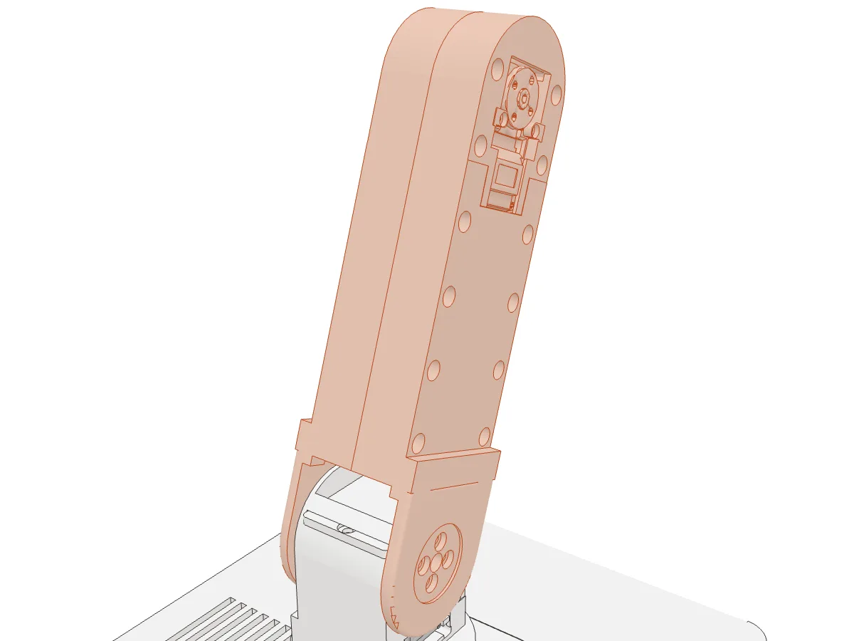
- Fit the lower arm's two cheeks over the shoulder servo's driven and passive horns. Fix each cheek with four M3 × 4.
- Fit the driven horn's centre screw.
Check These screws are deliberately short: longer ones would hit the bottom of the horn's thread before clamping. Make sure each horn is fully seated and each screw clamps the arm.
Put the wrist servo in the upper arm
- 4× M2 × 6 screws (gear face)
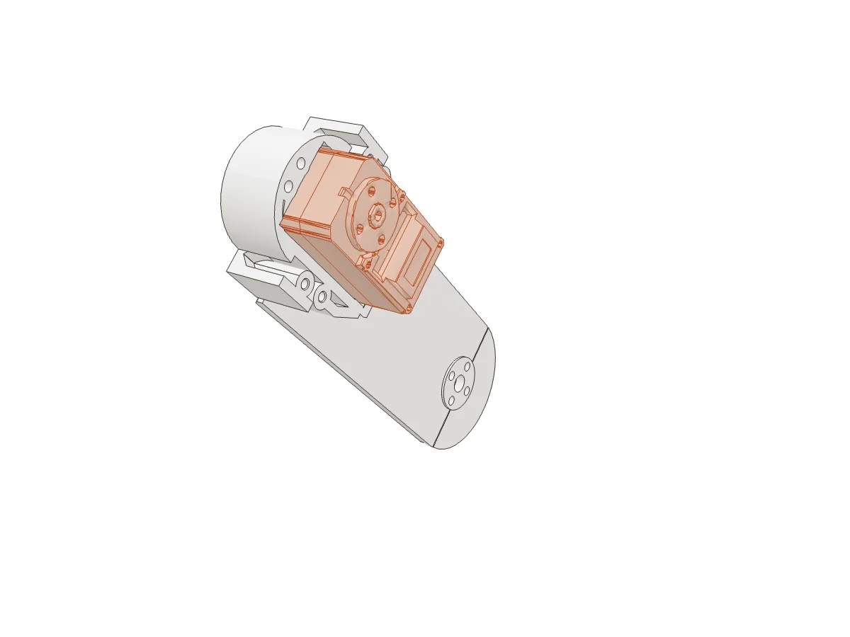
The upper arm carries the wrist servo (ID 4) and is built the same way as the lower arm.
- Plug the cable coming up from the elbow into the wrist servo. Leave its other socket empty: the neck servo's cable plugs into it in step 27.
- Lay the servo in the left half, gear face against that half, and fit the four gear-face M2 × 6.
- Bend the cables over the 2 mm rod and lay one in each channel.
Close the upper arm
- 4× Dowel pins, 3 × 6 mm
- 4× M3 × 20 screws (seam)
- 2× M2 × 6 screws (plain face)
- 4× Printed flush plugs
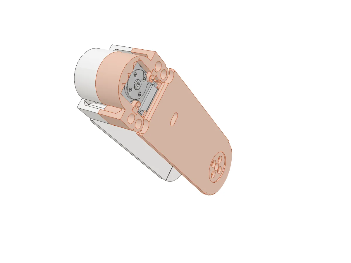
- Fit the four dowel pins, close the right half, and fit the four M3 × 20 seam screws.
- Fit the two plain-face M2 × 6, then press in the four plugs.
Fit the upper arm to the elbow
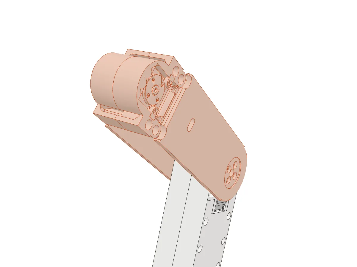
- 8× M3 × 4 button-head screws
- 1× Servo centre screw (supplied)
- Fix the upper arm's cheeks to the elbow horns with eight M3 × 4, four per side.
- Fit the elbow's driven-horn centre screw.
Stage 4 of 5 · steps 22–33Build the head
The head has two movements. The wrist tilts it up and down; the neck servo (ID 5) inside the head turns it left and right around a horn that is screwed to the top of the neck post. Build the head on the table first, then fit it to the neck post, then fit the post to the wrist.
Put the neck servo in its cartridge
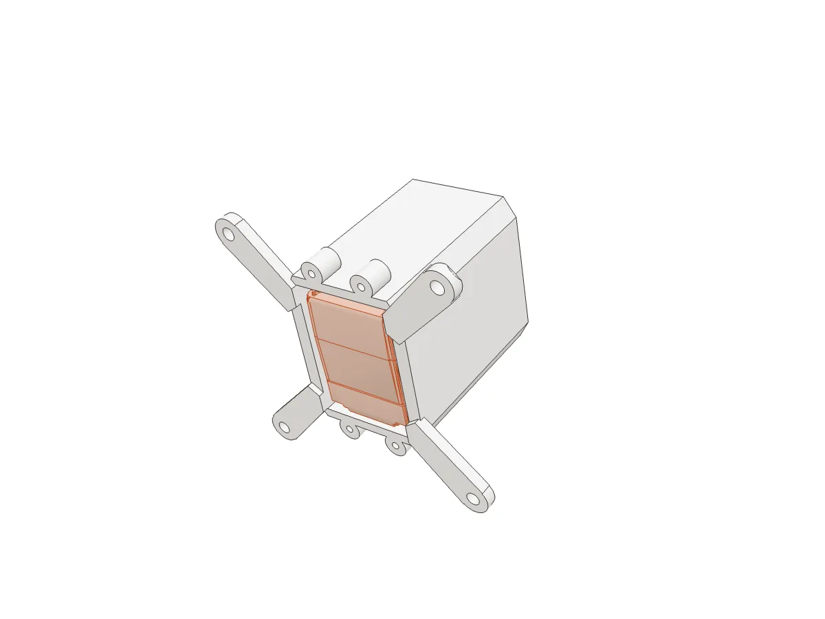
- Plug a servo cable into the neck servo and leave its other end free. It will connect to the wrist servo in step 27, so you can build the whole head on the table. The neck servo is the last in the chain, so its second socket stays empty.
- Slide the servo into the cartridge (17) from the open front, without its horn: the box is too tight for a servo with the horn already fitted. Its output faces down, towards the round opening in the bottom of the cartridge.
Fit the neck horn through the opening
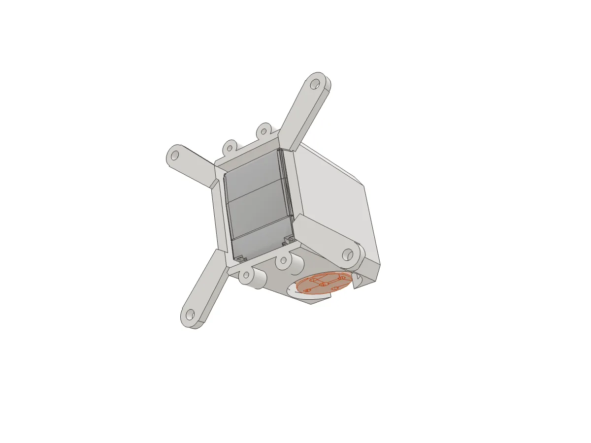
- 1× Servo centre screw (supplied with the servo)
- Turn the cartridge over. Through the round opening in its bottom, press the metal horn onto the servo's output (the gear side).
- Fit the horn's centre screw through the same opening.
Why this order The cartridge only has room for the bare servo. Fitting the horn through the opening afterwards is the only way to get both in.
Fit the cartridge retainer
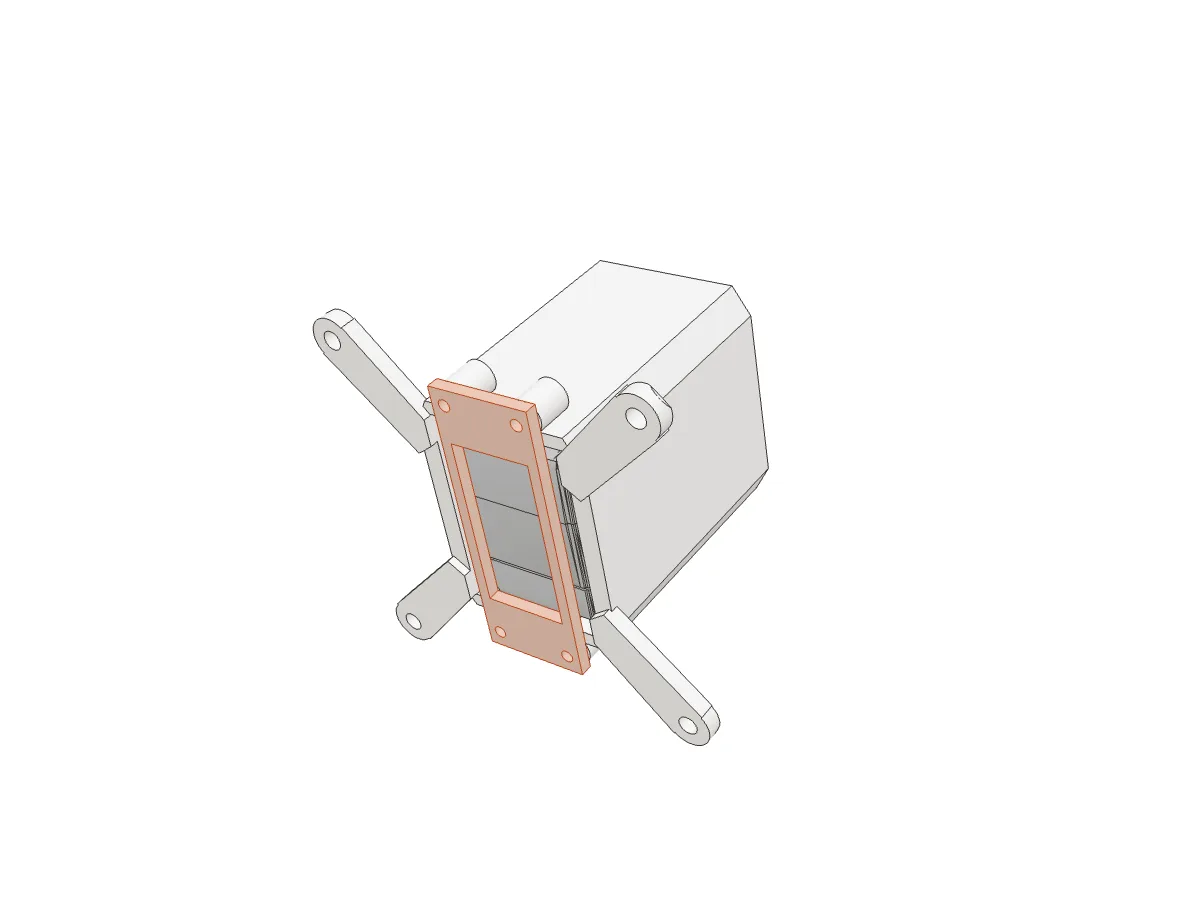
- 4× M2 × 6 screws
The retainer (18) is the narrow rectangular plate that closes the front of the cartridge and holds the servo in.
- Hold the retainer across the front of the cartridge, lining up its four holes with the four small holes in the cartridge.
- Fit four M2 × 6 through the retainer into the cartridge and tighten gently. The retainer presses the servo back against its stop, so it can't rattle.
Fit the cartridge into the head shell
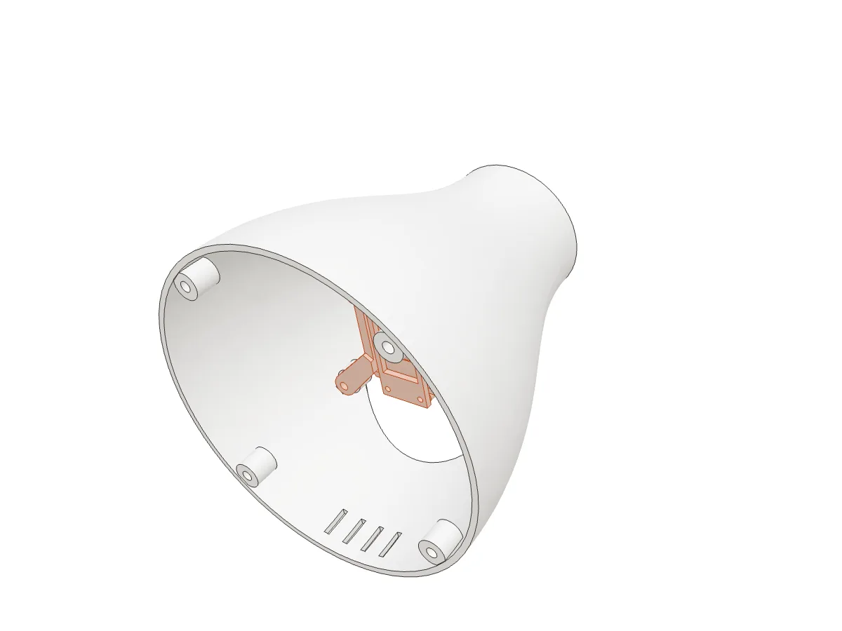
- 4× M3 × 6 button-head screws
- Pass the cartridge into the head shell (19) through the open front, horn first, so the horn sits over the round opening in the bottom of the shell. Lead the servo cable's free end out through that opening.
- Line up the cartridge's four ears with the four deeper inserts and fit four M3 × 6 from the front.
Fit the head onto the neck post
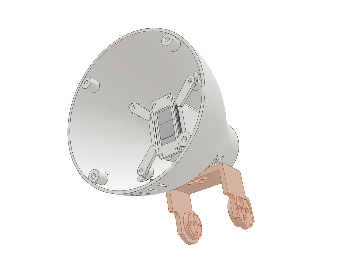
- 4× M3 × 5 button-head screws
The top of the pitch fork's neck post (16) screws to the horn you fitted in step 23. The four screws go in from underneath, through the deep holes in the post.
- Lower the head onto the post so the post's top sits flat against the horn, and turn the head until the four holes line up with the horn's holes. The head should face straight forward, along the fork. Keep the servo cable beside the post, not trapped between the post and the horn.
- From underneath, fit four M3 × 5 up through the post into the horn. A long, thin hex key or screwdriver reaches down the holes.
Screw length Use M3 × 5 here, not the M3 × 4 used at the other horns. The top of the post is 2.9 mm thick, so an M3 × 4 would only reach about 1 mm into the horn's thread. An M3 × 5 reaches about 2 mm, which is what the CAD is designed for.
Fit the head to the wrist
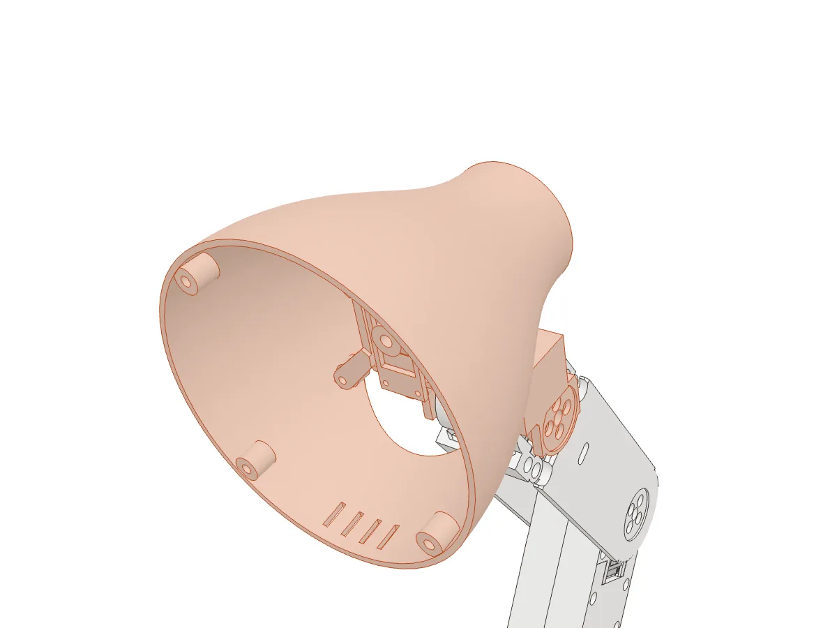
- 8× M3 × 8 button-head screws
- 1× Servo centre screw (supplied)
- Plug the neck servo's cable into the empty socket on the wrist servo, at the top of the upper arm.
- Fit the pitch fork over the wrist horns and fix it with eight M3 × 8, four per side, then the wrist centre screw.
- Turn the head left and right and tilt it up and down by hand. The cable should have enough slack for both without pulling.
Why longer screws The wrist fork is wider than the other joints' parts, so its screws need to be 8 mm long to reach the horn, where the shoulder and elbow use 4 mm.
Fit the camera to the cassette
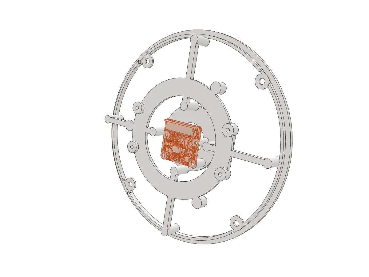
- 4× M2 × 4 screws
The camera, LED ring and speaker all mount on one removable front piece, the cassette (20). Build it on the table, not inside the head.
- Connect the camera's ribbon cable to the camera first, while it is easy to reach.
- Place the camera on the back of the cassette, lens through the centre opening, and fit four M2 × 4. Check the lens is centred.
Fit the LED ring
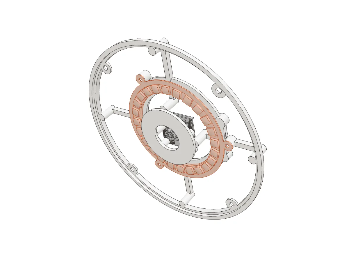
- 3× M2 × 4 screws
- Solder the ring's wires first. It has three pads you need: power (5 V), ground (GND) and data in (DIN; not DOUT). Solder a wire to each, long enough to run down the arm to the Pi in the base with slack at every joint. Measure along the lamp with the arm stretched out.
- Turn the cassette over and rest the LED ring on its pads on the front, LEDs facing forward.
- Lay the retaining ring (24) over it and fit three M2 × 4. The retainer should hold the board, not press on the LEDs or the solder joints.
Fit the speaker
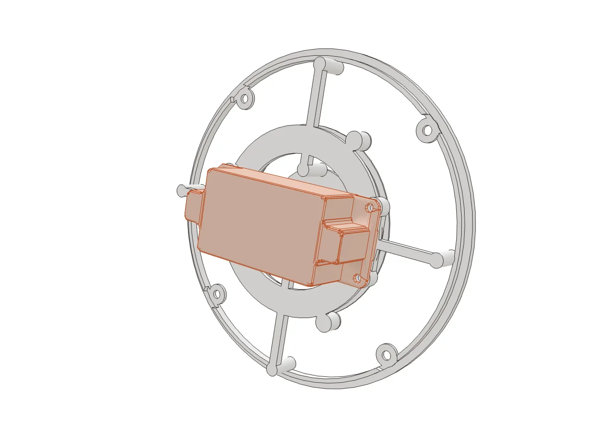
- 4× M2.5 × 6 screws
- Connect the speaker's wires.
- Place the speaker on its four posts behind the camera and line up all four holes before tightening any of them.
- Fit four M2.5 × 6.
Run the head's cables to the base
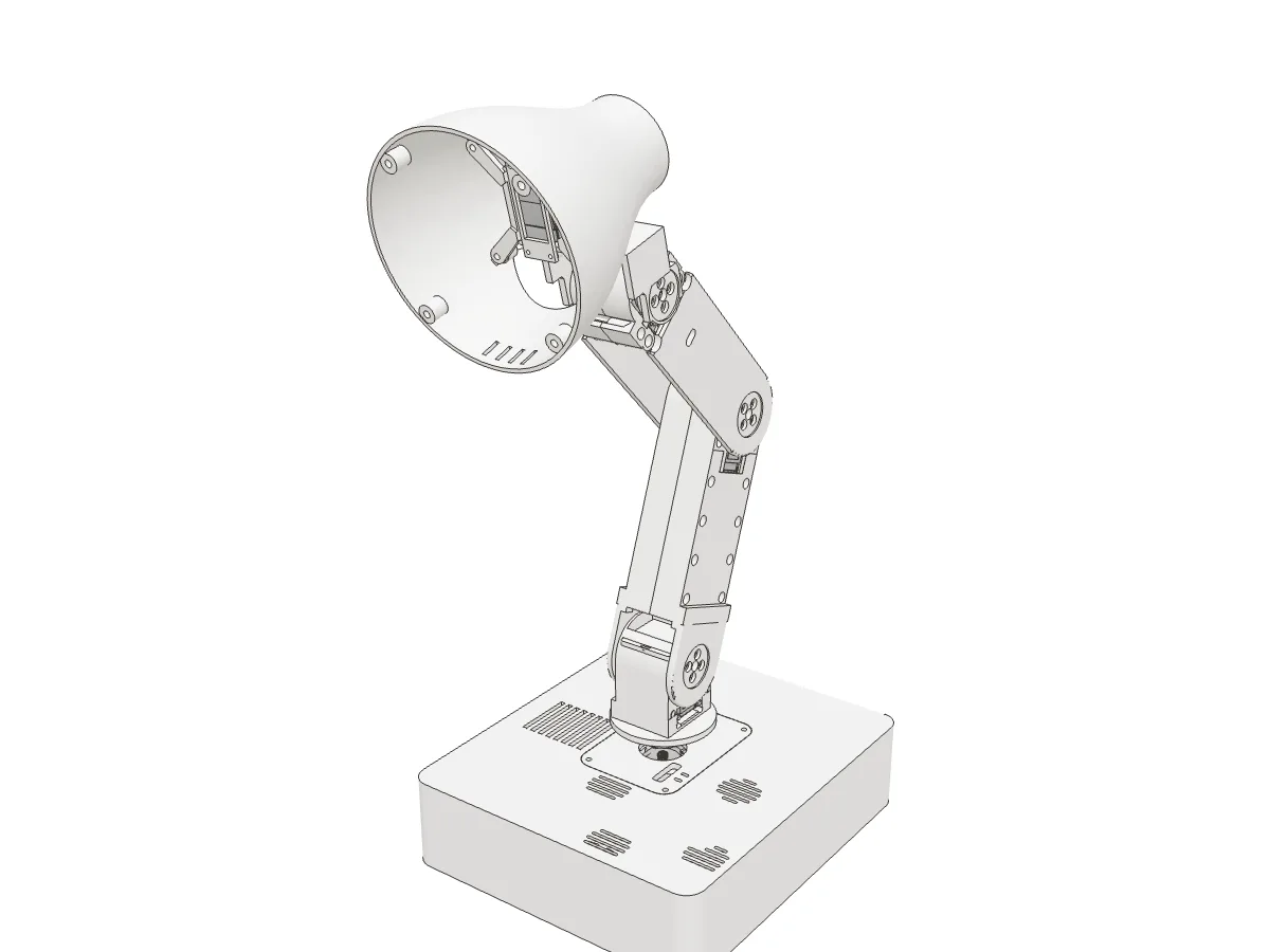
Three sets of wires leave the head and go down to the base. Route them now, with the cassette held just in front of the head.
- Camera: lead the camera's ribbon out of the back of the head and down the outside of the lamp to the back of the base. Join it to the 500 mm Pi 5 camera cable with the cable joiner. Pass the cable in through one of the openings in the rear panels and plug it into the Pi's camera socket.
- LED ring and speaker: run their wires down along the arm, then through the slot in the yaw servo carrier into the base. Connect the LED ring to the Pi's header: 5 V to pin 4, ground to pin 30, data to pin 32 (GPIO12). Connect the speaker to the microphone array's speaker output.
- Leave a loop of slack at the neck, wrist, elbow and shoulder, then move each joint by hand through its full range to check nothing pulls tight.
Careful Wiring the LED ring the wrong way round can damage the ring or the Pi. Check 5 V, ground and data twice.
Fit the cassette into the head
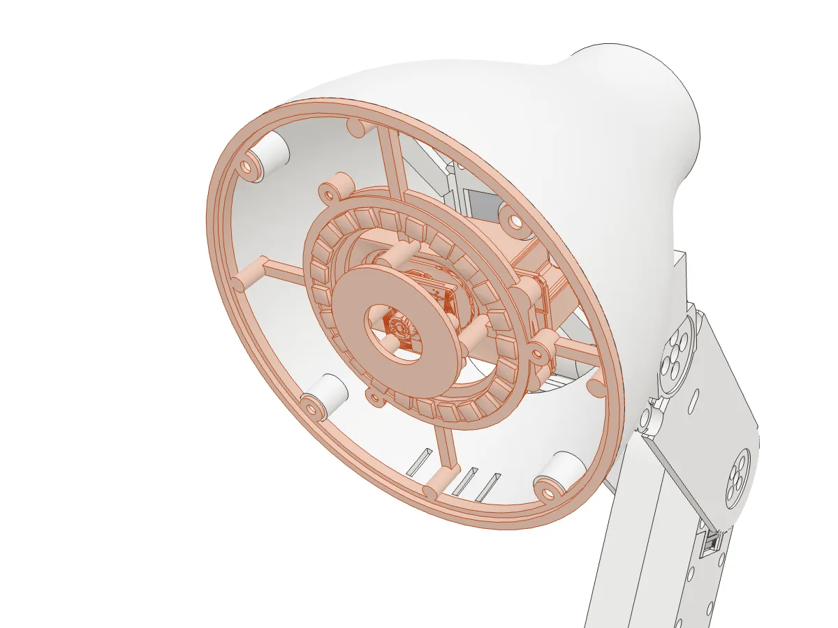
- Tuck the cables in and slide the cassette into the front of the head, speaker first, until its rim sits on the four inserts near the head's rim.
- Don't fit any screws yet: the diffuser goes on top and the same screws hold both.
Fit the diffuser
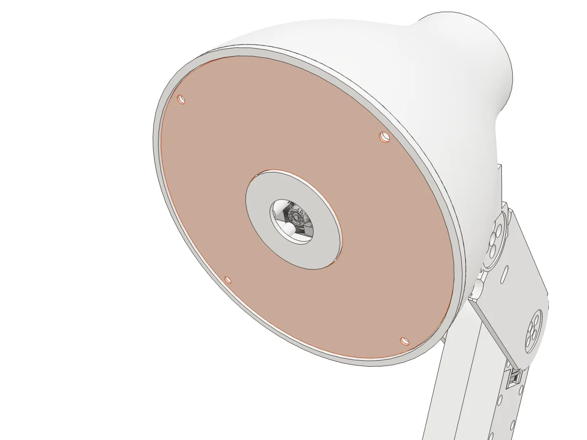
- 4× M3 × 6 button-head screws
The diffuser (21) is the thin disc in front of the LEDs that softens their light; the camera looks through the hole in its middle.
- Lay the diffuser over the cassette and line up its four holes with the cassette's.
- Fit four M3 × 6 through the diffuser and the cassette into the inserts, tightening opposite corners in turn. Stop when the rim is seated; overtightening bends the diffuser.
Service To reach the inside of the head later, undo these four screws and lift the front away. The camera, LEDs and speaker come with it.
Stage 5 of 5 · steps 34–37Finish and bring it to life
Check the wiring
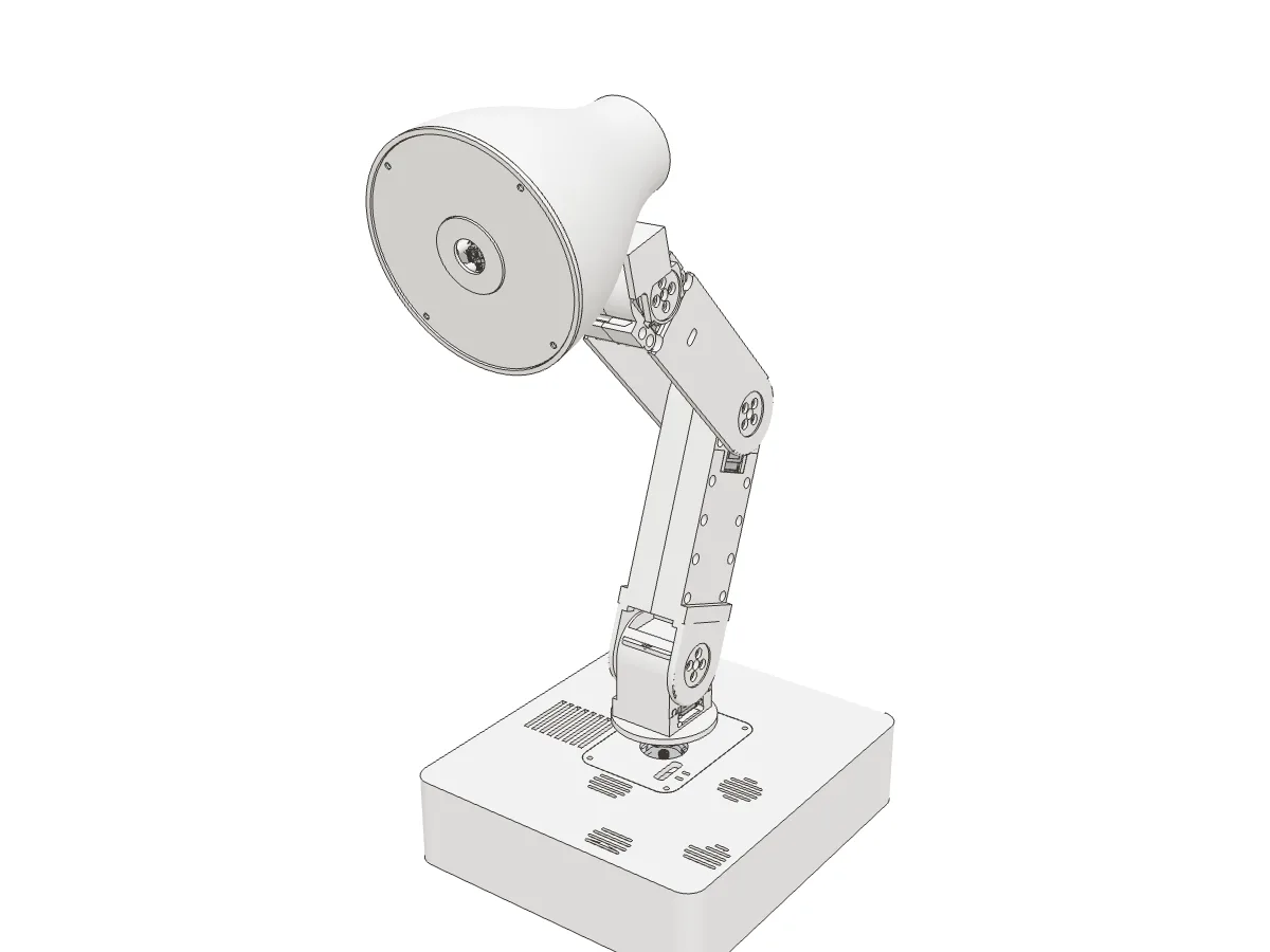
Before closing anything, check every connection against this list with both supplies unplugged.
| Connection | Made in |
|---|---|
| Servo chain: servo board → base → shoulder → elbow → wrist → neck | Steps 6–27 |
| Servo board to Pi, by USB | Step 10 |
| Microphone array to Pi, upper USB-A socket | Steps 9–10 |
| 6 V supply to servo board; USB-C supply to Pi | Step 11 |
| Camera: ribbon → joiner → 500 mm Pi 5 cable → Pi camera socket | Step 31 |
| LED ring to Pi pins 4 (5 V), 30 (ground), 32 (data) | Step 31 |
| Speaker to the microphone array's speaker output | Step 31 |
Move every joint gently by hand through its full range one more time. Nothing should pull tight or catch.
Fit the joint caps
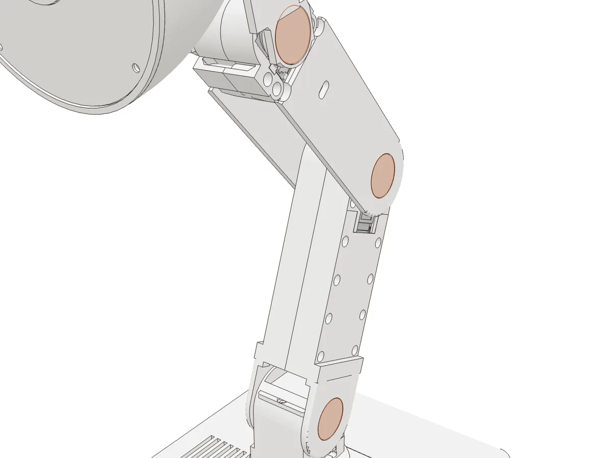
- 18× Thin removable adhesive tabs, 3 per cap
The six caps cover the horn screws at the shoulder, elbow and wrist. Stick three thin tabs on the back of each cap, keeping them away from the screw-head recesses, and press it into place. The tabs let you peel a cap off later.
Close the base
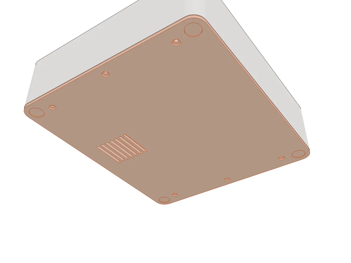
- 6× M3 × 6 button-head screws
Fit the bottom cover with six M3 × 6, tightening them evenly a little at a time.
Set the zero position and start Orion
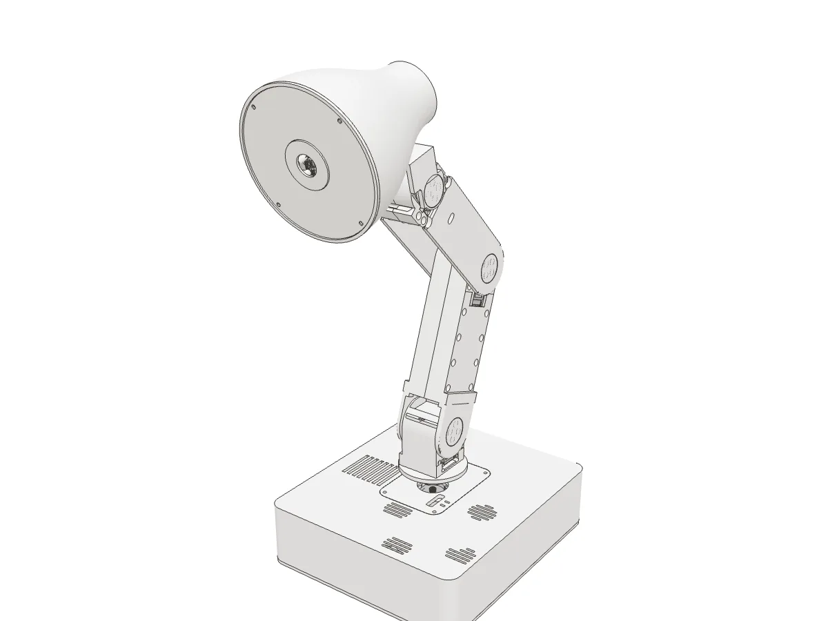
Each servo stores its own zero position. Orion sets it with the lamp folded into a fixed rest pose, so every joint agrees with the software no matter how the horns were fitted.
- Plug in both supplies and connect to the Pi over SSH. The services are still stopped from the install; if you have started them since, stop them:
sudo systemctl stop orion-voice-stack orion-vision orion-studio-gateway orion-listener oriond - Fold the lamp into its rest pose, as in the pictures: the lower arm lies back along the base, the upper arm folds forward over it, the head rests down on the shoulder housing, and the head and base both face forward.
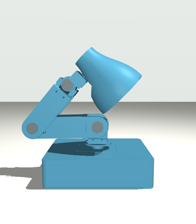
Side 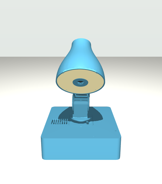
Front - Let go, keep the table still, and write the zero positions. It watches the joints for 2 seconds first:
Each joint should print a line ending inoriond servo zero(rest 2047); verified. - Read the joints back. All five should be close to 0:
oriond --check - Clear the space around the lamp and start Orion. It rises slowly to its home pose:
sudo systemctl start oriond orion-listener orion-studio-gateway orion-voice-stack orion-vision - Run the installer's check, which reads every servo and service in one go:
curl -fsSL https://raw.githubusercontent.com/mofe64/orion/main/scripts/install.sh | bash -s -- --check
Careful Get the rest pose right before zeroing. A wrong fold gives the joints the wrong zero and can strain them when Orion moves. If you're unsure, compare with the pictures again.
If zeroing fails
Zeroing checks its own work. If something goes wrong, Orion puts back the old zero positions and leaves the motors switched off, so you can fix the cause and run oriond servo zero again. The message tells you what went wrong:
| If it says | It means | Do this |
|---|---|---|
| “lamp is moving; let it settle” | A joint moved during the 2-second check. | Let go of the lamp, make sure it rests on its own and nothing is touching the table, and run it again. |
| “Expected one USB servo adapter” | The Pi can't see the servo board, or sees more than one. | Check the servo board's USB cable. If you really have two adapters, add --port with the right device. |
| “… reads 1980; expected 2047 +/-8” (any joint, any number) | A servo didn't take its new zero. | Run it again. If the same joint fails twice, check its cable and that the 6 V supply is on. |
| “Servo 3 is not an STS3215”, or a timeout | A servo didn't answer: unplugged, wrong ID, or no power. | Check the chain connections and the 6 V supply. A servo with the wrong ID has to be unplugged on its own and given its ID again (step 5). |
| “Offset recovery incomplete … Inspect the bus before retrying” | The old zeros couldn't all be put back, usually because a cable came loose mid-way. | Unplug the power, check every servo connection, then run zeroing again; it writes fresh zeros for every joint. |
After a successful zero, oriond --check should show all five joints close to 0. If one is far off, the lamp probably wasn't in the rest pose: fold it again and repeat.
Final checks
- Every insert is flush and firm, and no boss has split.
- Small screws grip without spinning, and every board sits flat.
- No loose support scraps or filament strands are left inside the head or base.
- Every horn is seated and no servo rocks in its holder.
- Cables have slack at every joint and nothing catches when the lamp moves.
- The front of the head comes off for service.
Something unclear or wrong? Open an issue on GitHub so the next builder benefits.